Understanding the difference between series and parallel circuits is essential in physics and electrical engineering. These two circuit types determine how electric current flows, how voltage is distributed, and what happens when one component fails.
From holiday lights to household wiring, nearly every electrical system uses one of these configurations — or a combination of both.
This guide explains series vs parallel circuits in simple terms, including how they work and where they’re used.
What Is a Series Circuit?
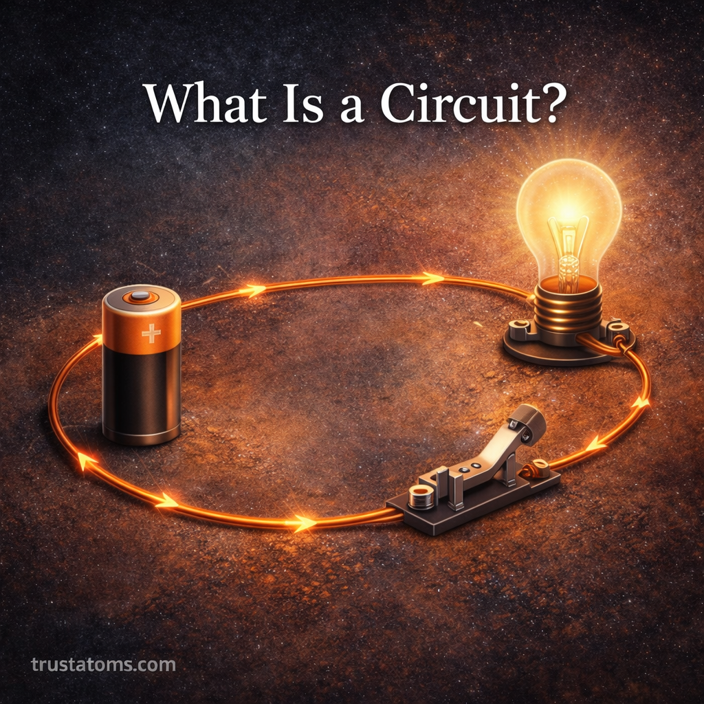
A series circuit connects components one after another in a single path.
There is only one route for electric current to flow.
Key Characteristics of Series Circuits
- One continuous loop
- Same current flows through all components
- Voltage is divided among components
- If one component fails, the entire circuit stops
Think of it like a single-lane road. If something blocks the road, traffic stops completely.
Example of a Series Circuit
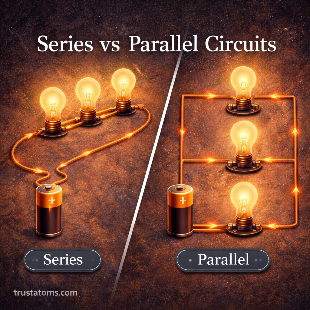
Imagine three light bulbs connected in a line to a battery:
Battery → Bulb 1 → Bulb 2 → Bulb 3 → Back to battery
If Bulb 2 burns out:
- The circuit becomes open
- No current flows
- All bulbs turn off
Older string lights often used this design.
What Is a Parallel Circuit?
A parallel circuit connects components across multiple branches.
There are multiple paths for electric current to flow.
Key Characteristics of Parallel Circuits
- Multiple pathways
- Same voltage across each branch
- Current splits among branches
- If one component fails, others continue working
Think of it like a multi-lane highway. If one lane closes, traffic can still move through the others.
Example of a Parallel Circuit
Imagine three light bulbs connected to a battery on separate branches:
- Each bulb has its own path
- All bulbs receive the same voltage
- If one bulb burns out, the others stay lit
This is how household wiring works.
Major Differences Between Series and Parallel Circuits
Here’s a clear comparison:
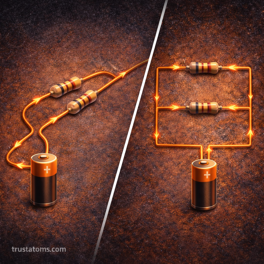
Current Flow
- Series: Same current through all components
- Parallel: Current divides among branches
Voltage Distribution
- Series: Voltage is shared between components
- Parallel: Each branch receives full voltage
Reliability
- Series: One failure shuts everything down
- Parallel: Other branches continue working
Brightness of Bulbs (in simple examples)
- Series: Bulbs may appear dimmer as more are added
- Parallel: Bulbs maintain normal brightness
Advantages and Disadvantages
Series Circuit Advantages
- Simple to design
- Requires fewer wires
- Easy to build for basic setups
Series Circuit Disadvantages
- Not reliable for large systems
- Components depend on each other
Parallel Circuit Advantages
- More reliable
- Components work independently
- Consistent performance
Parallel Circuit Disadvantages
- Requires more wiring
- Slightly more complex to design
Why Homes Use Parallel Circuits
Household electrical systems use parallel circuits because:
- Lights stay on if one burns out
- Appliances operate independently
- Each device receives full voltage
If homes were wired in series, turning off one appliance would shut off everything else.
Can Circuits Combine Both Types?
Yes.
Many real-world systems use combination circuits (also called series-parallel circuits). These contain both series and parallel sections.
Electronics, vehicles, and industrial systems commonly use this mixed design for efficiency and control.
When to Use Each Type
Use a series circuit when:
- You need simplicity
- All components must operate together
- It’s a basic demonstration setup
Use a parallel circuit when:
- Devices must operate independently
- Reliability is important
- You are wiring homes or buildings
Final Thoughts
The difference between series and parallel circuits comes down to how current flows and how components are connected.
- Series circuits have one path.
- Parallel circuits have multiple paths.
Series circuits are simple but less reliable. Parallel circuits are more complex but allow independent operation and consistent voltage.
Understanding these two fundamental designs is a key step in mastering basic physics and electrical systems.